Privacy statement: Your privacy is very important to Us. Our company promises not to disclose your personal information to any external company with out your explicit permission.
Abstract: DSPs need to extend the asynchronous serial communication interface when communicating with multiple peripherals. Taking TMS320C6711 as an example, the ST16C554 asynchronous serial transceiver is used to introduce the design scheme of the most advanced C6000 series DSP and multi-channel RS232, RS485/422 device communication, and the hardware and software implementation examples are given.
The external interface between the DSP and the computer can be mainly divided into a serial communication port and a parallel communication port. Serial communication includes communication using protocols such as RS232, RS485/422, USB, and IEEE1394, and parallel communication includes communication using protocols such as IEEE488 and IEEE1248. This paper mainly introduces the design and implementation of DSP multi-channel RS232 and RS485/422 communication systems, and applies this system to the three-dimensional angular rate measurement combination of fiber optic gyro.
1 system design
1.1 System Block Diagram
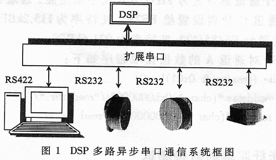
Figure 1 is a block diagram of a DSP multi-channel asynchronous serial communication system. The computer receiving end is a general-purpose data acquisition card, which adopts RS485/422 protocol with the DSP, and the communication speed can reach 921.6kBPS. The RS232 protocol is adopted between the fiber optic gyroscope and the DSP, and the communication rate can reach 115.2kBPS. The system can realize communication between DSP and three RS232 devices and one RS485/RS422 device. 
1.2 Introduction to TMS320C6711
The TMS320C6000 series DSP chip is mainly a super processing chip introduced for signal processing of mobile communication base stations. The TMS320C6711 with 200MHz clock completes the 1024-point FFT algorithm with a time of 66μs, which is an order of magnitude faster than the traditional DSP chip, so it is used in civilian and The military field has broad application prospects. In the highly intelligent applications of military communications, electronic countermeasures, radar systems, precision guided weapons, etc., the processing power of this chip has an irreplaceable advantage [2]. TMS320C67XX is a floating point series in TMS320C6000. TMS320C6711 is a chip with better cost performance. Like other TMS320C6000 series chips, the chip provides two multi-channel synchronous buffer serial ports. It does not provide an asynchronous serial port, so asynchronous serial port expansion is required.
1.3 Communication scheme design
Almost all digital signal processors currently provide one or more serial interfaces. However, most DSP chips provide a synchronous serial port. In practical applications, DSP is also required to perform asynchronous serial communication with multiple peripherals. For example, serial data transmission between a PC or a fiber optic gyroscope requires a DSP system with multiple UART serial interfaces; The general-purpose I/O port is used to form the serial port, and the baud rate is set by the software (this method is often used when the DSP is not busy). However, when these two I/O lines are occupied or the real-time requirements for communication are high, the DSP should implement high-speed serial communication by extending the asynchronous communication chip.
In view of this situation, this paper studies and implements a simple and reliable asynchronous serial port expansion method, which is to extend the UART chip on the parallel bus of DSP and realize asynchronous data transmission with hardware. The advantage of this method is that the software implementation is simple, at the cost of extending other devices on the bus. Because this solution is to realize asynchronous serial communication between DSP and four peripherals, considering the convenience of hardware connection and software programming, it adopts four-channel ST16C554 serial asynchronous transceiver and multi-channel electronic conversion chip MAX3245E. In this way, four-way asynchronous serial communication can be realized with the simplest hardware connection and software programming.
1.4 Introduction to ST16C554
ST16C554 is EXAR's asynchronous communication chip, its main features are as follows [3]:?
· Compatible with ST16C454, ST68C454, ST68C554, TL16C554;
· 16 bytes of transmit and receive FIFOs;
· Four-channel selection of independent control and transmission control;
Four optional receive FIFO interrupt trigger levels;
· Standard MODEM interface;
· Up to 1.5M baud rate, its baud rate generator is programmable;
· The data bit length is 5, 6, 7, 8 and the stop bit length is 1, 1.5, 2;
· With even parity, odd parity or no parity mode.
The ST16C554 can not only perform parallel/serial conversion of data sent by the DSP, but also serial/parallel conversion of data received from peripherals or MODEMs, enabling simultaneous transmission and reception of four independent channels. At the same time, ST16C554 also has four independent 16-byte receive and transmit FIFOs, which can effectively reduce CPU interrupts by enabling FIFO and setting FIFO interrupt trigger level, improving system efficiency and reliability. 
2 system hardware design
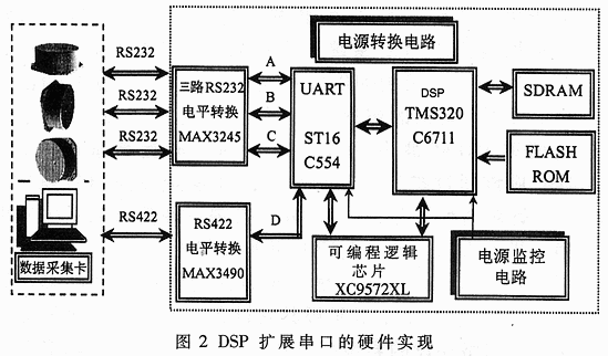
The hardware design block diagram of the system is shown in Figure 2. The hardware system is composed of a power conversion circuit, a power supply monitoring circuit, a DSP, an SDRAM, a FLASH ROM, a UART, a level conversion chip, and a programmable logic chip. The power conversion circuit completes a 5V to 3.3V/1.8V DC-DC conversion, providing power to all low voltage chips in the system design. The power monitoring circuit is used to monitor all the power supply voltages of the system. When the power supply voltage is lower than the rated value, the DSP and UART are reset to protect the chip. The ST16C554 UART simultaneously completes the communication of four channels A, B, C and D. The three channels A, B and C complete the asynchronous transmission and reception of three RS232 ports, the baud rate is 115.2kBPS, and the D channel completes the communication of RS485/422. The baud rate is 921.6kBPS, and the baud rate can be set separately in the corresponding control register. When the external crystal oscillator is 14.7456MHz, the above baud rate setting can be conveniently performed. The multi-channel UART-RS232 level shifting device MAX3245 has a conversion rate of up to 1MBPS. The programmable logic chip is XILINX's CPLD (XC9572XL), which is used to complete all logic control in the system.
When the DSP reads and writes to the UART, it must involve the conversion of the actual address of the UART in the DSP. In this scheme, the CE3 space of the DSP is set to 8-bit asynchronous mode, and the corresponding address range is 0xB0000000~0xBFFFFFFF. Corresponding to the UART read and write operation address and the strobe address of four independent channels, the corresponding offset is added. The corresponding read and write and chip select logic is done by the CPLD. The corresponding internal logic of the CPLD is as follows:
——CE3 COMMUNICATION SPACE ADDR=B0000000—BFFFFFFF
D3: CSF3<=CE3 OR(NOT EA5);--Channel C FOG3ADDR=B0000008
CSF2<=CE3 OR(NOT EA4);--Channel B FOG2ADDR=B0000004
CSFl<=CE3 OR(NOT EA3);--Channel A FOG1ADDR=B0000002
CSF4<=CE30R(NOT EA2);--Channel D RS422ADDR=B0000001
Among them, CSF1~CSF4 are channel selection signals, which are active low; EA2~EA5 are DSP address lines.
3 software design
The system software design includes the initialization and communication protocols of the PC, TMS320C711 and ST16C554. The program of the TMS320C711 initialization ST16C554 will be given below in conjunction with the hardware of the system. The main task of initialization is to set the parameters required to operate each channel, including the number of data bits of the data string during serial communication, the number of stop bits, parity, and so on. In addition, you need to set the baud rate and interrupt mode for sending and receiving.
Where RHR is the receive holding register and THR is the transmit holding register. The FCR is the FIFO control register and is set to FIFO enable. IER is the interrupt enable register, used in conjunction with FCR, set to FIFO interrupt mode, or set to DMA mode. The LSR is a linear status register that detects if there is data in the FIFO or RHR by querying the lowest bit. The DLL and DLM are baud rate setting registers, and the baud rate is set by dividing the crystal oscillator. When the highest bit of the LCR is 1, the DLL and DLM settings can be changed.
Taking channel A as an example, the C language program initialized by the DSP to ST16C554 is as follows:
/*FOG1*/
*(char*)0xb0000032=0x80;/*lcr=80*/
*(char*)0xb0000002=0x08;/*dll=08*/
*(char*)0xb0000012=0x00;/*dlh=00*/
*(char*)0xb0000032=0xlb;/*lcr=1b*/
*(char*)0xb0000022=0x01;/*fcr=01*/
*(char*)0xb0000012=0x01;/*ier=01*/
*(char*)0xb0000022=0x03;/*fcr=01*/
*(char*)0xb0000022=0x01;/*fcr=01*/
All four channels are set to FIFO mode and interrupt enable. Channel A, channel B, and channel C are respectively set to RS232 with a baud rate of 115.2 kBPS; channel D is set to RS485/422 with a baud rate of 921.6 kBPS.
The data reading procedure of DSP for channel A is as follows:
While((readtp & 0x01)!=0)
{readdata=*(char*)0xb0000002;/*read rhr */
Readtp=*(char*)0xb0000052;/*read 1sr*/
} 
4 docking test with fiber optic gyroscope
The system was docked with the fiber optic gyroscope and the test showed that the system fully met the design requirements.
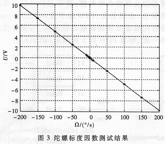
Figure 3 is the scale factor test result of the gyroscope. The abscissa is the input angular rate, and the ordinate is the voltage output value of the DSP output data after D/A conversion. The curve in the figure is based on the input and output data with the minimum two. Multiply fitted to find.
The software and hardware of the system have been debugged and successfully applied to the aerospace fiber optic gyro angular velocity measurement system. The solution can flexibly and efficiently complete the asynchronous serial communication between the DSP and multiple PCs or sensors (ie, multiple fiber optic gyros), and can also implement a standard interface with the MODEM. In addition, if the EDMA function of the DSP is used to complete the transmission and reception, the system performance can be further improved and high-speed serial communication can be realized [4].
December 29, 2023
December 28, 2023
October 14, 2022
E-mel kepada pembekal ini
December 29, 2023
December 28, 2023
October 14, 2022

Privacy statement: Your privacy is very important to Us. Our company promises not to disclose your personal information to any external company with out your explicit permission.

Fill in more information so that we can get in touch with you faster
Privacy statement: Your privacy is very important to Us. Our company promises not to disclose your personal information to any external company with out your explicit permission.